
In short
Size the coherence length against the optical path difference between the arms, not against the size of your setup. A moving mirror changes that difference by twice its travel.
In a displacement interferometer the wavelength is your ruler, so wavelength accuracy and stability translate directly into measurement error.
For measurements in air over longer paths, the refractive index of the air often limits you before the laser does.
Interferometry is the application where laser specifications stop being marketing and start being arithmetic. Every number on the datasheet maps onto something you can measure at the output: how far you can move before the fringes wash out, how much of your reading is real displacement, and how much is the laser drifting. This article goes through those numbers in the order you need them.
Coherence length and the path difference
Fringe contrast depends on how far the two beams are out of step when they recombine. The quantity that governs it is the optical path difference between the measurement arm and the reference arm. The physical size of the setup only matters in so far as it drives that difference.
Lc ≈ c / (π · Δν)
Lorentzian line, field correlation fallen to 1/e · 10 MHz gives about 9.5 m
| Linewidth | Coherence length* | Workable path difference as a rough guide |
|---|---|---|
| 1 MHz | approx. 95 m | long-range displacement, large machine axes |
| 10 MHz | approx. 9.5 m | most machine tool and stage metrology |
| 100 MHz | approx. 0.95 m | bench setups with matched arms |
| 1 GHz | approx. 9.5 cm | short, carefully balanced arms only |
| 10 GHz | approx. 9.5 mm | effectively balanced-arm work |
*Calculated for a Lorentzian line with the 1/e field-correlation definition. The cruder rule L = c/Δν is also in common use and gives roughly three times these values. Neither is wrong, they answer slightly different questions, but a number from one convention must not be compared against a number from the other. We go through the units and conversions in laser linewidth and coherence length explained.
Two things that catch people out
A moving mirror doubles its travel. The light makes the trip to the mirror and back, so 250 mm of stage travel changes the optical path difference by 500 mm. Size the coherence length against the latter.
Contrast does not fall off a cliff. Visibility decreases gradually as the path difference grows. Coherence length is a scale, not a hard limit, and how much contrast your detection electronics still tolerate is part of the specification.
The wavelength is your ruler
A displacement interferometer counts fringes and multiplies by a known wavelength. That makes the wavelength the calibration standard of the whole instrument, and any relative error in it appears unchanged in the result:
ΔL / L = Δλ / λ
A relative wavelength error of 1 × 10⁻⁶ gives 1 µm of error per metre measured
This is where linewidth and wavelength stability stop being interchangeable. Linewidth is the spectral width of the line and sets your coherence length. Wavelength stability is how far the centre of that line drifts over a stated period and temperature range, and that is what enters the equation above. A source can be narrow and still drift, or comparatively broad and sit very precisely where it should.
Which of the two dominates depends on what you are doing. For fringe counting over a short path with loose tolerance, neither is likely to be your limit. For traceable dimensional metrology the wavelength has to be known and held, which is why frequency-stabilized sources exist and why the classic reference wavelength in this field is the stabilized helium-neon line near 633 nm.
The air in the beam path
Interferometers in air do not measure geometric distance. They measure optical path, which is geometric distance multiplied by the refractive index of the medium. Air has a refractive index of roughly 1.00027 at room conditions, and that figure moves with temperature, pressure and humidity.
| Change in the beam path | Approximate change in refractive index | Resulting error over 1 m |
|---|---|---|
| 1 K temperature | about 0.9 × 10⁻⁶ | roughly 0.9 µm |
| 1 hPa pressure | about 0.27 × 10⁻⁶ | roughly 0.27 µm |
| 10 % relative humidity | well below the two above in the visible | usually negligible by comparison |
Values are order-of-magnitude figures for visible light at around 20 °C and standard pressure. The accepted way to calculate them for a specific setup is the Edlén equation or its later revisions, and good interferometer systems either compensate from measured environmental data or run the beam path in vacuum.
The practical consequence: over a one metre path in uncontrolled air, a one kelvin temperature error produces a larger deviation than the wavelength uncertainty of a well-specified laser. Buying a more stable source does not help if the air in the beam path is not measured or controlled. Work out which term dominates in your setup before you specify the laser.
Mode behaviour and why hops hurt
An interferometer integrates phase. If the source jumps from one cavity mode to a neighbouring one, the wavelength changes abruptly and so does the phase relationship between the arms. In a fringe-counting system that shows up as a step in the reading that no amount of filtering recovers, because the information is simply gone.
| Term | What it promises | What it does not promise |
|---|---|---|
| Single transverse mode, TEM00 | a clean, near-Gaussian spatial profile | anything about the spectrum |
| Single longitudinal mode | one cavity mode oscillating at a given moment | that it will stay on that mode as temperature or current change |
| Mode-hop-free | no jumps within the stated conditions | anything outside those conditions, so ask what they are |
| Narrow linewidth | the numeric width of the line | where the centre of the line sits over time |
For interferometry you generally want all four properties, and they have to be asked for separately. The phrase single frequency is used loosely in the market and on its own does not tell you whether the source stays on one mode across your operating range.
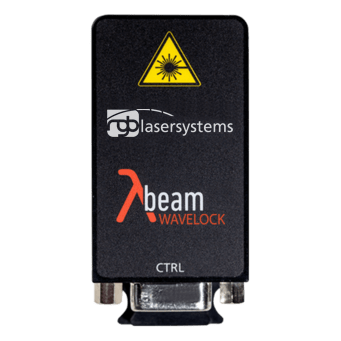 For long path differences
Lambda Beam Wavelock
Wavelength stabilized modules · linewidth, coherence length and stability stated per variant
See specs
Beam quality, polarization and power
| Parameter | Why it matters here | What to ask for |
|---|---|---|
| Beam quality | Wavefront distortion reduces fringe contrast and produces position-dependent errors as the beam traverses the optics differently at different stage positions | M² and the beam mode, plus the beam diameter convention used |
| Polarization | Heterodyne systems separate the two frequencies by polarization. Imperfect separation produces periodic non-linearity in the reading, typically at the scale of fractions of a fringe | Extinction ratio at the relevant output, and after the fiber if there is one |
| Power stability | Phase, not amplitude, carries the measurement, so this is less critical than in intensity-based methods. It still affects signal quality and the reliability of fringe detection | A figure with the stated period and measurement point |
| Pointing stability | Beam walk changes which part of the optics the light passes through and therefore the apparent path | Specified over a temperature range, not just at a fixed point |
Power requirements are usually modest. Interferometers detect a beat signal rather than a faint return, and once the detector has enough light to give a clean signal, more power buys nothing. Where it does become a question is with poorly reflecting targets, long paths with beam spread, or systems that split one source across several axes.
A specification checklist
- Maximum optical path difference, including the factor of two for any moving mirror. This sets the coherence length, and therefore the linewidth.
- Required measurement uncertainty, expressed as a relative figure. Compare it against the wavelength stability and against the environmental terms from the section above.
- Operating temperature range of the instrument, not of the laboratory. Every stability figure is conditional on it.
- Homodyne or heterodyne. Heterodyne architectures add requirements on polarization purity and on the frequency offset.
- Delivery format. Fiber coupling takes alignment out of assembly, but a polarization maintaining fiber brings its own launch and connector requirements.
- Whether the beam path is in air, and if so, how the refractive index is compensated.
Frequently asked questions
What laser is used for interferometry?
Historically the frequency-stabilized helium-neon laser near 633 nm, which is still the reference in traceable dimensional metrology. Stabilized diode and DPSS modules now cover a large part of the field at lower cost and in far smaller packages. What matters is not the technology but the combination of coherence length, wavelength stability and stable single longitudinal mode operation.
How much coherence length do I need?
At least the maximum optical path difference between the arms, with margin for the contrast your detection still tolerates. Remember that a moving mirror changes the path difference by twice its travel, and state which coherence length convention the figure you are comparing against uses.
Is a narrower linewidth always better?
Not automatically. Narrower usually means more expensive, more sensitive to temperature and more vulnerable to optical feedback. If your path difference is a few centimetres, a source with a kilohertz linewidth buys a specification nothing in the measurement uses. Size it to the path difference you actually have.
Why does my reading drift when nothing moves?
In air, the most common cause is the refractive index of the beam path changing with temperature or pressure rather than anything in the laser. Check that first. The other candidates are wavelength drift of the source, thermal expansion of the mechanical loop that carries the optics, and mode hops.
Does the wavelength itself matter?
Mainly through resolution and through the optics and detectors available. A shorter wavelength gives a smaller fringe spacing and therefore finer intrinsic resolution per fringe, while longer wavelengths tolerate rougher surfaces and more turbulence. Established component ecosystems around 633 nm and 532 nm are a practical argument of their own.
Specifying a source for an interferometer?
Tell us your maximum path difference, the uncertainty you need and whether the beam runs in air. We will say which specification actually limits you and which one you can stop paying for.