

In short
Fringe spacing follows from wavelength and crossing angle. Always state whether an angle is the half-angle or the full angle between the beams, the two differ by a factor of two in the result.
The wavelength sits in the velocity equation, so wavelength drift turns straight into a calibration error.
Both beams have to be mutually coherent where they cross. If they travel different path lengths, coherence length becomes a hard requirement rather than a detail.
Laser Doppler velocimetry measures the speed of a fluid without touching it, by watching how light scatters off small particles carried along in the flow. The technique is also sold as laser Doppler anemometry, and the two names describe the same measurement. It is one of the few optical methods where the laser is not just a light source but part of the measuring instrument itself.
The fringe model in one page
In the dual-beam arrangement that dominates practical systems, one laser beam is split in two and the halves are brought to a crossing point inside the flow. Where they overlap they interfere and produce a set of parallel light and dark planes. A particle passing through scatters light that is modulated as it crosses those planes, and the modulation frequency gives the velocity component perpendicular to them.
df = λ / (2 · sin κ)
fD = u / df = 2 · u · sin κ / λ
κ is the half-angle, measured between one beam and the bisector. The full angle between the two beams is 2κ
State which angle you mean
Both conventions are in circulation. Some texts write the formula with the half-angle κ as above, others with the full beam intersection angle. Substituting a full angle into a half-angle formula changes the fringe spacing by a factor of 2·cos κ, so close to two at small crossing angles and still about 1.9 at a full angle of 30°. The error survives all the way into the reported velocity.
When you read a figure from a datasheet or a paper, check which convention it uses before you compare it with your own.
Worked through for a 532 nm source, with the half-angle convention:
| Full angle between beams | Half-angle κ | Fringe spacing at 532 nm | Doppler frequency per 1 m/s |
|---|---|---|---|
| 5° | 2.5° | 6.10 µm | 164 kHz |
| 10° | 5° | 3.05 µm | 328 kHz |
| 20° | 10° | 1.53 µm | 653 kHz |
| 30° | 15° | 1.03 µm | 973 kHz |
The table shows the trade you are making with the crossing angle. A wider angle gives finer fringes and therefore more signal cycles per particle, which helps the frequency estimate. It also raises the Doppler frequency your electronics have to handle, and it shortens the measurement volume along the optical axis, which can be an advantage for spatial resolution and a problem for signal rate.
Why the wavelength is part of your calibration
Rearranged for what you actually want, the relationship reads u = fD · λ / (2 sin κ). The velocity is the measured frequency multiplied by a geometric factor and by the wavelength. With the geometry fixed, a relative error in the wavelength produces the same relative error in the velocity:
Δu / u = Δλ / λ
0.1 nm of drift at 532 nm is 1.9 × 10⁻⁴, so about 0.02 % on the velocity
For most flow measurements 0.02 % is far below the other error terms, and wavelength stability is not where you should spend money. It becomes relevant when the uncertainty budget gets tight, when the source is a free-running diode whose centre wavelength moves with temperature by something in the range of a few hundredths to a few tenths of a nanometre per kelvin depending on the diode type, or when the instrument has to hold calibration across a wide ambient range without recalibration.
The much larger error source in practice is the crossing angle, because it enters through a sine and has to be known for the specific optical head rather than assumed from a drawing. That is why commercial systems are calibrated as a unit rather than from first principles.
Coherence: the one that bites
The fringes only exist if the two beams are still mutually coherent when they meet. That puts a requirement on the difference in optical path length between the two arms, measured from the splitter to the crossing point.
| Source | Rough coherence length | What that means for the optical head |
|---|---|---|
| Multi-mode diode | order of a millimetre | path lengths must be matched to well under a millimetre, which is demanding in a fibre-coupled head |
| Single longitudinal mode diode, hundreds of MHz | order of tens of centimetres | comfortable for a free-space head, workable with matched fibres |
| Narrow line DPSS, around 10 MHz | around 10 m | path matching stops being a design constraint |
Figures use the 1/e field-correlation convention for a Lorentzian line, the same one we use in laser linewidth and coherence length explained. Other conventions give values that differ by roughly a factor of three, so compare like with like.
Where this matters most is in fibre-delivered probes. Two fibres cut to nominally the same length can differ by centimetres, and in a traversing system the path through the optics changes as the head moves. With a long coherence length none of that is visible. With a short one, fringe contrast varies with position and the signal quality follows it, which is an unpleasant fault to diagnose because nothing is broken.
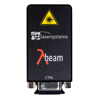 A common choice for single component systems today
532 nm Lambda Beam, narrow line version
DPSS green · narrow line variants for long path differences · free space or fiber coupled
See specs
Beam quality and the measurement volume
The measurement volume is the small ellipsoid where the two focused beams overlap. Its size follows from the beam waist and the crossing angle, and the fringe pattern inside it is only uniform where the wavefronts are close to flat, which is near the waist.
- The waists should coincide with the crossing point. If they do not, the wavefronts are curved where the beams meet, the fringe spacing varies across the volume, and a particle produces a frequency that depends on where it passed. That is a systematic error, not noise, so averaging does not remove it.
- A clean fundamental mode keeps the volume well defined. Higher order content spreads the intensity and blurs the boundaries of the volume, which shows up as a wider scatter in the measured velocities. Ask for M² and the beam mode rather than the label TEM00 on its own.
- Both beams need matching polarization. Fringe contrast depends on the component of the two fields that share a polarization direction. Orthogonally polarized beams cross without producing fringes at all.
- Beam diameter conventions differ. A diameter quoted at 1/e² of peak intensity and one quoted at full width half maximum are not the same number. Check which one a datasheet uses before you put it into an optical design.
Power, seeding and direction
LDV detects light scattered from individual particles, so the signal depends on the laser power, the particle size and refractive index, the collection optics and the scattering direction. Forward scatter collects far more light than back scatter, but requires optical access on both sides of the flow, which many test rigs do not allow.
There is no general power figure that fits every setup. What decides it is the signal-to-noise ratio at the detector for the smallest particle you need to follow, in the scattering geometry you are able to build. Treat power as something you work out backwards from that, and note that seeding quality is often the cheaper lever: well-chosen particles can be worth more than a larger laser.
Direction ambiguity. The fringe model as described gives the same frequency for a particle moving one way and for one moving the other. Systems that need the sign resolve it by shifting the frequency of one beam, classically with an acousto-optic modulator, so that a stationary particle produces the shift frequency and movement appears as a deviation above or below it. If your flow reverses or recirculates, this is not optional, and it belongs in the specification of the optical head rather than of the laser.
What to specify
| Parameter | Why it matters | How to state it |
|---|---|---|
| Coherence length | Decides whether the two arms have to be path matched | With the convention used, and compared against the worst-case path difference in the head including any fibres |
| Longitudinal mode behaviour | A mode hop changes the wavelength and therefore the velocity calibration mid-measurement | Ask for mode-hop-free operation with the conditions it holds under, not just the words single frequency |
| Beam quality | Defines the measurement volume and the uniformity of the fringes within it | M², beam mode, and the waist diameter with its convention |
| Polarization | Fringe contrast depends on it, and fibre delivery can scramble it | Extinction ratio at the output you actually use |
| Power stability | Affects signal rate and validation rate rather than the velocity itself | With a stated period and measurement point |
| Wavelength stability | Enters the velocity equation directly | Drift over a stated period and temperature range. Usually a minor term, but quantify it rather than assume |
For instrument builders, two further points belong in the specification from the start: the ambient temperature range the finished device has to work in, because every stability figure above is conditional on it, and the delivery format, since a fibre-coupled source moves alignment out of series assembly at the cost of some optical power and a path-length requirement. Both are covered on our OEM laser module page.
Frequently asked questions
What is the difference between LDV and LDA?
None in substance. Laser Doppler velocimetry and laser Doppler anemometry describe the same measurement, and which term you meet depends mostly on the manufacturer and the region. Phase Doppler anemometry is a different thing: it extends the method to measure particle size as well as velocity, using the phase difference between two detectors.
Which wavelength is used for laser Doppler velocimetry?
Historically the field was dominated by argon ion lasers, with the 488 nm and 514.5 nm lines, and by helium-neon at 632.8 nm. Compact solid state sources have since taken over much of that ground, and green around 532 nm is now a common single choice, helped by good detector response and a mature component ecosystem. Multi-component systems use several wavelengths at once so that each velocity component can be separated by colour, classically 488 nm and 514.5 nm, often with a red line around 633 nm as the third. The physics does not favour a particular wavelength, it enters only through the fringe spacing and the scattering efficiency of the seeding.
How much laser power does LDV need?
There is no general figure. It follows from the smallest particle you need to detect, the collection geometry, and how much signal-to-noise ratio your processor needs for a valid burst. Forward scatter needs far less power than back scatter for the same signal. Improving the seeding is often cheaper than increasing the power.
Can a multi-mode diode be used?
It can, if the optical path lengths of the two arms are matched to well within its coherence length, which is typically of the order of a millimetre. Some compact probes are built exactly that way. It constrains the mechanical design considerably, and it makes the head sensitive to anything that changes a path length, so the usual choice for a flexible instrument is a single longitudinal mode source.
Why does my signal rate drop when I traverse the probe?
Several candidates, and they are worth checking in this order: the measurement volume has moved out of the seeded region, the optical access window is distorting one beam more than the other at that position, the beam waists no longer coincide at the crossing point, or the path difference between the arms has changed enough to reduce fringe contrast. The last one only appears with sources whose coherence length is comparable to the path difference.
Building an LDV or LDA probe?
Tell us your crossing geometry, the path difference in the head and whether you deliver through fibre. We will tell you what coherence length the design actually needs and where you can stop paying for specification.